Description
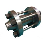
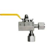
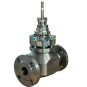
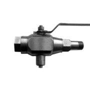
Клапаны регулирующие БИРС Б01
На больших диаметрах трубопровода и при небольшом расходе экономически выгодно установить клапаны регулирующие меньшего диаметра, в этом случае конструкция клапана предусматривает применение фланцев корпуса, каналы которых имеют вид усечённых конусов с диаметром внутреннего основания, равным условному диаметру клапана, а внешнего – равным требуемому диаметру трубопровода (т.н. диффузоры и конфузоры). Это позволяет, например, на диаметр трубопровода 300 мм, использовать клапан диаметром DN100 мм.
Таблица 1. Стандартная спецификация
|
Модель привода |
Электрический БИРС 14; диафрагменный БИРС 37; электромагнитный БИРС 50; ручное управление |
|||||||||||||||
|
Модель клапана |
УРПС БИРС Б01 |
|||||||||||||||
|
DN |
мм |
10 |
15 |
20 |
25 |
32 |
40 |
50 |
65 |
80 |
100 |
150 |
200 |
250 |
||
|
Ход |
мм |
10 |
20 |
20 |
20 |
25 |
25 |
25 |
30 |
40 |
40 |
50 |
50 |
75 |
||
|
K vy |
См. таблицу условной пропускной способности клапанов УРПС БИРС Б01 |
|||||||||||||||
|
PN |
МПа |
1,6; 2,5; 4,0; 6,3; 10,0; 16,0 |
||||||||||||||
|
Соединение к трубе |
Фланцевое (выступ-впадина) |
|||||||||||||||
|
Корпус |
Ст.20; ст.09г2с; ст.12Х18Н10Т, ст.10Х17Н13М2Т, прочие стали под заказ |
|||||||||||||||
|
Дроссельная пара |
Ст.12Х18Н10Т, 10Х17Н13М2Т, прочие под заказ |
|||||||||||||||
|
Т регулир. среды |
˚С |
Варианты от -60 до +450 в зависимости от материалов клапана |
||||||||||||||
|
Т окр. среды |
˚С |
Варианты от -60 до +70 в зависимости от материалов корпуса |
||||||||||||||
Особенностью конструкции клапанов УРПС БИРС Б01 является производство их из высококачественного стального проката. Входной инструментальный контроль сырья позволяет получать гарантированно стабильные показатели. Неразрушающий контроль сварных соединений обеспечивает гарантированное отсутствие протечек по корпусу в течение гарантийного срока службы изделия.
Ответная часть клапана обеспечивает управлением им с помощью различных средств управления. Характеристики клапана максимально адаптированы под применение прямоходных электроприводов БИРС 14 и диафрагменных пневмоприводов БИРС 37.
Регулирующие клапаны УРПС БИРС Б01 соответствуют требованиям стандарта ТР ТС 012. Изделию присвоена категория IIGbcT4.
Таблица 2.Условная пропускная способность Kvy регулирующих клапанов УРПС БИРС Б01.
|
DN, мм |
Условная пропускная способность м³/час |
|||||||||||||||||
|
Номера дроссельных узлов при написании формулы изделия |
||||||||||||||||||
|
1 |
2 |
3 |
4 |
5 |
6 |
7 |
8 |
9 |
10 |
11 |
12 |
13 |
14 |
15 |
16 |
17 |
18 |
|
|
10 |
0,006 |
0,016 |
0,04 |
0,1 |
0,16 |
0,25 |
0,4 |
0,6 |
1 |
1,6 |
||||||||
|
15 |
0,006 |
0,016 |
0,04 |
0,1 |
0,16 |
0,25 |
0,4 |
0,6 |
1 |
1,6 |
2,5 |
|||||||
|
20 |
0,006 |
0,016 |
0,04 |
0,1 |
0,16 |
0,25 |
0,4 |
0,6 |
1 |
1.6 |
2,5 |
4 |
6,3 |
|||||
|
25 |
0,006 |
0,016 |
0,04 |
0,1 |
0,16 |
0,25 |
0,4 |
0,6 |
1 |
1,6 |
2,5 |
4 |
6,3 |
8 |
||||
|
32 |
0,16 |
0,25 |
0,4 |
0,6 |
1 |
1,6 |
2,5 |
4 |
6,3 |
8 |
10 |
12 |
||||||
|
DN, мм |
Условная пропускная способность м³/час |
||||||||||||||||
|
Номера дроссельных узлов при написании формулы изделия |
|||||||||||||||||
|
19 |
20 |
21 |
22 |
23 |
24 |
25 |
26 |
27 |
28 |
29 |
30 |
31 |
32 |
33 |
34 |
35 |
|
|
40 |
20 |
25 |
32 |
||||||||||||||
|
50 |
32 |
40 |
50 |
||||||||||||||
|
65 |
50 |
63 |
80 |
||||||||||||||
|
80 |
100 |
125 |
|||||||||||||||
|
100 |
125 |
160 |
200 |
||||||||||||||
|
150 |
200 |
250 |
|||||||||||||||
|
200 |
250 |
320 |
400 |
500 |
630 |
||||||||||||
|
250 |
630 |
800 |
1000 |
||||||||||||||
Таблица 3. Массогабаритные размеры регулирующих клапанов УРПС БИРС Б01 с диафрагменным пневмоприводом БИРС 37 (без аксессуаров).
|
DN, мм |
|||||||||||||
|
10 |
15 |
20 |
25 |
32 |
40 |
50 |
65 |
80 |
100 |
150 |
200 |
250 |
|
|
PN, Мпа |
≤4,0 |
≤4,0 |
≤4,0 |
≤4,0 |
≤4,0 |
≤4,0 |
≤4,0 |
≤4,0 |
≤4,0 |
≤4,0 |
≤4,0 |
≤4,0 |
≤4,0 |
|
≥6,3 |
≥6,3 |
≥6,3 |
≥6,3 |
≥6,3 |
≥6,3 |
≥6,3 |
≥6,3 |
≥6,3 |
≥6,3 |
≥6,3 |
≥6,3 |
≥6,3 |
|
|
L, мм |
120 |
130 |
150 |
160 |
180 |
200 |
230 |
290 |
310 |
350 |
480 |
600 |
730 |
|
210 |
210 |
230 |
230 |
260 |
260 |
300 |
340 |
380 |
430 |
550 |
650 |
800 |
|
|
Н1, мм |
450 |
453 |
520 |
520 |
520 |
560 |
560 |
729 |
737 |
754 |
786 |
956 |
1100 |
|
455 |
458 |
520 |
520 |
525 |
560 |
560 |
739 |
744 |
764 |
799 |
1102 |
1200 |
|
|
D1, мм |
250 |
250 |
250 |
250 |
250 |
310 |
310 |
310 |
350 |
470 |
470 |
470 |
470 |
|
Вес, кг |
14,4 |
15,4 |
15,8 |
17,3 |
18,8 |
24,3 |
25,5 |
38,0 |
59,0 |
90 |
155 |
200 |
400 |
|
15,4 |
16,3 |
16,6 |
18,3 |
19,8 |
24,3 |
25,5 |
63,4 |
70,1 |
104 |
170 |
230 |
450 |
|
Таблица 4. Массогабаритные размеры регулирующих клапанов УРПС БИРС Б01 с электроприводом БИРС 14.
|
DN, мм |
|||||||||||||
|
10 |
15 |
20 |
25 |
32 |
40 |
50 |
65 |
80 |
100 |
150 |
200 |
250 |
|
|
PN, Мпа |
≤4,0 |
≤4,0 |
≤4,0 |
≤4,0 |
≤4,0 |
≤4,0 |
≤4,0 |
≤4,0 |
≤4,0 |
≤4,0 |
≤4,0 |
≤4,0 |
≤4,0 |
|
≥6,3 |
≥6,3 |
≥6,3 |
≥6,3 |
≥6,3 |
≥6,3 |
≥6,3 |
≥6,3 |
≥6,3 |
≥6,3 |
≥6,3 |
≥6,3 |
≥6,3 |
|
|
L, мм |
120 |
130 |
150 |
160 |
180 |
200 |
230 |
290 |
310 |
350 |
480 |
600 |
730 |
|
210 |
210 |
230 |
230 |
260 |
260 |
300 |
340 |
380 |
430 |
550 |
650 |
800 |
|
|
Н1, мм, не более |
515 |
520 |
520 |
595 |
600 |
620 |
650 |
660 |
690 |
1050 |
1060 |
1060 |
1075 |
|
550 |
560 |
560 |
610 |
620 |
650 |
660 |
670 |
710 |
1060 |
1080 |
1100 |
1100 |
|
|
А, мм |
174 |
174 |
174 |
174 |
174 |
174 |
184 |
184 |
184 |
198 |
198 |
198 |
198 |
|
Вес, кг, не более |
22 |
24 |
25 |
26 |
31 |
31 |
33 |
38 |
59 |
90 |
160 |
205 |
405 |
|
25 |
27 |
27 |
28 |
32 |
32 |
35 |
63 |
80 |
110 |
175 |
235 |
455 |
|
Условное обозначение клапана УРПС БИРС Б01 при заказе.
УРПС БИРС Б01.50.40.1.3.3.L.С, где
Б01 – клапан малогабаритный регулирующий
50 – условный диаметр, мм
40 – давление, атм
1 – материал корпуса 09г2с
3 – материал плунжера 12Х18Н10Т
3 – материал седла 12Х18Н10Т
L – линейная расходная характеристика
С – исполнение фланцев «выступ-впадина» по ГОСТ 33259