Description
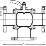
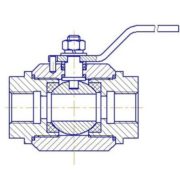
Globe valve cast BIRS Б02
The valves are designed to work at pressures (P) up to 4.0 MPa, nominal diameter (DN) from 15 mm to 250 mm For larger diameters and with a small flow of economically advantageous to install a valve of smaller diameter, in this case, the valve design provides for the use of flanges of the housing, the channels which have the form of truncated cones with an inner diameter of the base equal to the nominal size of the valve, and the external equal to the desired diameter of the pipeline (so-called diffusers and confusers). This allows, for example, the diameter of the piping 300 mm, use a valve with a diameter of DN100 mm.
Table 1. Standard Specification
|
Drive Model |
Electric BIRS 14; diaphragm BIRS 37; electromagnetic BIRS 50; manual actuation |
||||||||||||||
|
Valve Model |
URPS BEERS Б02 |
||||||||||||||
|
DN |
mm |
15 |
20 |
25 |
32 |
40 |
50 |
65 |
80 |
100 |
150 |
200 |
250 |
||
|
Stroke |
mm |
20 |
20 |
20 |
25 |
25 |
25 |
30 |
40 |
40 |
50 |
75 |
75 |
||
|
PN |
MPa |
1,6; 2,5; 4,0 |
|||||||||||||
|
Connection to the pipe |
flange mounting (ledge-slot) |
||||||||||||||
|
Body frame |
st.20GL; st.12Х18Н9ТL; st. 20L |
||||||||||||||
|
Throttle pair |
St. 12Х18Н10Т |
||||||||||||||
|
T medium |
˚С |
Options from -60 to + 450 |
|||||||||||||
|
Environment temperature, |
˚С |
Variation from -60 to +70 |
|||||||||||||
The design feature of the valve URPS BEERS Б02 is their production of quality steel castings in lost foam model. Input control of raw materials guarantees stable performance in the entrance process. Non-destructive testing of castings guarantees the absence of leaks in the casing within the warranty life of the product.
Valve counterpart is adapted for the application of various control means for linear electric power actuators BIRS 14 and diaphragm pneumatic actuators BIRS 37.
Valves URPS BEERS Б02 comply with the requirements TR CU 012. The product has category IIGbcT4.
Table 2. Conditional throughput Kvy valves URPS BEERS Б02.
|
DN mm |
Conditional capacity m ³/hour |
|||||||||||||||||||
|
Number of throttle nodes when writing the product formula. |
||||||||||||||||||||
|
1 |
2 |
3 |
4 |
5 |
6 |
7 |
8 |
9 |
10 |
11 |
12 |
13 |
14 |
15 |
16 |
17 |
18 |
19 |
||
|
15 |
1,7 |
2,3 |
3,1 |
3,5 |
4,2 |
4,6 |
5,8 |
7 |
||||||||||||
|
20 |
1,7 |
2,3 |
3,1 |
3,5 |
4,2 |
4,6 |
5,8 |
7 |
10,4 |
|||||||||||
|
25 |
5,8 |
7 |
10,4 |
16 |
||||||||||||||||
|
32 |
7 |
10,4 |
16 |
29 |
||||||||||||||||
|
40 |
10,4 |
16 |
29 |
32 |
||||||||||||||||
|
50 |
16 |
29 |
32 |
58 |
||||||||||||||||
|
65 |
29 |
32 |
58 |
98 |
||||||||||||||||
|
80 |
127 |
|||||||||||||||||||
|
100 |
206 |
|||||||||||||||||||
|
150 |
387 |
|||||||||||||||||||
|
200 |
765 |
|||||||||||||||||||
|
250 |
1060 |
|||||||||||||||||||